Die Design Menu
The following functions appear under the Die Design menu.
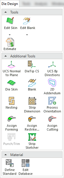
|
|
Function |
|
|
|
Create a skin (with no thickness) from an object. This enables clear and easy analysis of operations in the system. |
|
|
|
Blank a set of adjacent stitched and skinned faces on the extension of other sets of faces, using finite element analysis (FEA). |
|
|
|
Use this function to submit the collected data to the online estimation engine. |
|
|
|
Create a UCS by defining a plane that will be normal to its Z axis. |
|
|
|
Create a DieTip CS (Coordinate System) on a forming shape. |
|
|
|
Create a UCS by defining an origin point and two axes. |
|
|
|
Create a skin (with no thickness) from an object. This enables clear and easy analysis of operations in the system. |
|
|
|
Blank a set of adjacent (stitched) faces and creating a flat wire-body |
|
|
|
Create an offset path around a blanked part to add extra material around the perimeter. |
|
|
|
Place the blank forming shapes into the strip and lay them out. |
|
|
|
Define the dimensions of the strip (such as strip width, margins, start margin, and number of steps) and specify strip carrier requirements |
|
|
|
Create the forming shape by defining the appropriate transfer shape over a selected blank. |
|
|
|
Define single axis bending, multi axis, rib, emboss, extrusion, dart, and gusset forming operations. |
|
|
|
Define single axis restriking, multi axis restriking, flattening, coining, and CAM form operations in an efficient manner. |
|
|
|
Mark the curves that represent various cutting operations to efficiently estimate the various cutting operations. |
|
|
|
Define the various blanking punches that will define the Blank shape. |
|
|
|
Create a sketch for the carrier. |
|
|
|
Define the material standard (such as Generic, UNI, DIN, and so on). |
|
|
|
Edit the material database. This enables you to view and edit the properties of materials, and to add or delete materials. |


